
ENGINE DISMANTLING FOR DECARBONISING - A Group Models
Decarbonising and ‘top overhaul' of an engine is extremely simple, but it should be carried out only when the engine really needs it. The usual symptoms are an increased tendency to ‘pink’ (a metallic knocking when under heavy load) due to the building-up of carbon on the tops of the pistons and inside the cylinder heads, a general falling-off of power noticeable mainly on hills, and a tendency for the engine to run hotter than usual.
It is first necessary to remove the petrol tank. To do this turn off the petrol taps and detach the petrol pipes. If the speedometer is mounted in the tank, disconnect the drive by releasing the strainer bolt under the tank, raising the speedometer clear of the tank and unscrewing the knurled nut connecting the drive to the instrument. At the same time, disconnect the cable for the speedometer light. The tank is secured to the frame by a bolt through the steering head lug and another through the seat lug at the rear of the frame top tube. When these bolts are removed, the tank can be taken off. The tanks on certain models are quickly detachable and it is only necessary to slacken the nuts to enable the tank to be lifted at the rear end and withdrawn from the frame. On Swinging Arm Models it is only necessary to remove the central retaining bolt beneath the rubber plug on top of the tank. On A10 and all Swinging Arm Models a metal strap beneath the tank joins the two halves and this must be removed to allow the tank to be withdrawn.
Next detach the high tension leads and remove the sparking plugs. Disconnect the steady-stays from the cylinder head to the frame, and then take off the carburetter by removing the flange bolts and sliding it off sideways after freeing it from the rubber sleeve which connects it to the air cleaner. By unscrewing the ring nut at the top of the carburetter, the slide can be pulled right out and tied up to the top tube out of the way. while the main body of the instrument can be completely removed. By unscrewing the exhaust pipe and silencer brackets to the frame, the pipes and silencers can be removed complete. Note that the silencer brackets are attached by means of the pillion footrest bolts on models with rigid frame.
A7 Models up to Engine No. ZA7-1H92
Remove the rocker box connecting links and oil feed pipe. The rocker boxes are bolted to the head by bolts above and studs and nuts from underneath. Take off all nuts and bolts and lift the rocker boxes clear. Remove the hardened valve end caps. (A.7 standard models only).
The cylinder head holding-down bolts can now be removed. There are seven of these, including the central one which is inclined at an angle, and which should be removed first, and replaced last. The head unit is attached to the cylinder block at the rear by means of two inverted studs, and the nuts must be removed from these before the head can be lifted off. These nuts are situated between the fins, adjacent to the inlet manifold.
A10 Models and A7 Models after Engine No. AA7-101
Remove the rocker box oil feed pipe. The rocker box is held in position by four bolts on the outside, one inside and one stud with nut and washer at each comer.
Remove the inspection covers, take out the bolts. Remove the nuts and washers. On 650c.c. models it is necessary to remove the top stud for the rear inspection cover and flats are formed on the stud for this purpose. The box can now be lifted dear of the cylinder head.
When the rocker box is removed the nine cylinder head bolts will be exposed. Remove the bolts, carefully noting the position of the various lengths of bolt. Fig. A6 a.
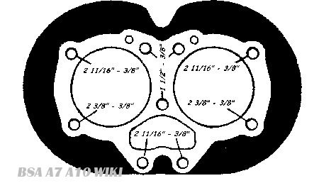
Fig. A6a
All Models
The cylinder head unit can now be removed. If it shows a tendency to stick, a few light taps with a wooden mallet under the exhaust ports will loosen it There is no necessity to remove the separate inlet manifold fitted to Shooting Star and Road Rocket models.
Rotate the engine by means of the kickstarter until the pistons are at the top of their stroke. and remove the carbon deposit with a suitable scraper, taking care not to damage the piston crowns,
All traces of carbon must be cleaned from the cylinder heads and valve ports. Where the head is an aluminium casting, particular care must be taken to ensure that the head is not scored or the joint faces damaged.
Grinding in Valves
Using Service Tool 61-3340 compress the valve springs until the split collets can be removed. When the collets are out, the valve springs and top collar can be lifted from the valve stem,
Check the play of the valves in the guides. If it is excessive the valve guides should be replaced and it may be necessary to change the valves at the same time. The old guides may be driven out from the inside and the new ones may be driven in from the outside of the cylinder head by means of the valve guide fitting punch, Service Tool No. 61-3265. When removing guides from the aluminium heads, the head should first be heated in a degreaser or hot water.
If new valve guides have been fitted or deep pit marks appear, the valve seats in the cylinder head should be re-cut When pitting in the valve heads is deep, they should be re-faced. Then the valves can be ground in with fine grinding compound, each valve to its own seat.
Smear a small quantity of grinding compound (obtainable from any garage or accessory shop) over the face of the valve, and return the valve to its seat. Note that a light spring inserted under the valve head greatly facilitates the grinding-in operation, allowing the valve to lift and be rotated to a new position periodically. Hold the valve with the special tool provided in the tool kit, and rotate the valve backwards and forwards whilst maintaining a steady pressure. The valve should be raised and turned to a new position after every few strokes. Grinding should be continued until the valve seat and face show a uniformly smooth matt surface all round. Valve grinding without re-facing should only be attempted if pitting is not deep.
Before replacing the valves and springs all traces of grinding compound must be removed from both face and seat, and the valve stems smeared with engine oil.
Valve Springs
After a period of several thousand miles it may be desirable to renew the valve springs as these tend ultimately to lose their efficiency due to heat If the springs are renewed whilst decarbonising, it will save dismantling specially to replace them at a later date.
Valve Rockers
To remove the rockers from the rocker boxes, if this should be required for any reason. it is only necessary to undo the acorn nuts on the rocker spindles, and also the banjo oil pipe unions on the rocker spindles, if fitted, and tap the spindles out, applying a small centre punch to the threaded ends exposed when the nuts are removed, so as to avoid .damaging the threads. Careful note should be kept of the rocker assembly for replacement, The various washers must be inserted in the correct order (see Fig. A.7)
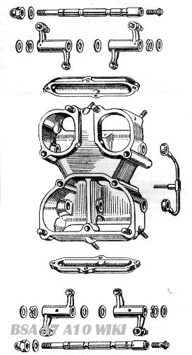
(A10 Models and A7 Models after Engine No. AA7-101)
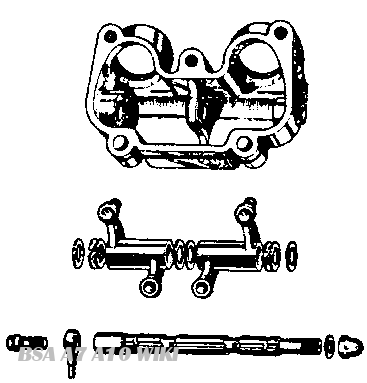
(A7 Models up to Engine No. ZA7-1H92)
Fig. A7. The Rocker Assembly
Cylinder Block
In the ordinary course of events it should rarely be necessary to remove the cylinder block, since top overhaul, already described, usually suffices to keep the machine in first-class working condition. In any case, this operation is difficult to carry out without the help of an assistant, and unless the condition of the engine indicates that the pistons, rings or cylinder bores require attention, the cylinder block should not be disturbed.
Symptoms indicating faulty piston rings might include heavy oil consumption, poor compression (but only if the valves are in good order; otherwise they are much more likely to be the cause) and excessive piston slap when warm. This latter might be due to worn bores, which could be checked without removing the block, if the pistons were moved to bottom dead centre, thus exposing the bores for examination and measurement
To remove the cylinder block, undo the cylinder base nuts, turn the engine until the pistons are at bottom dead centre, and then, preferably getting astride the machine, care-fully lift the block up until the pistons are clear of the bores. While this is being done, get an assistant to steady the pistons as they emerge and to relieve you of the weight of the block, so that it may be lifted clear. When the block is removed, cover the mouth of the crankcase with rag to prevent dust and grit falling in. To remove a piston from its connecting rod it is first necessary to take out one of the gudgeon pin circlips. This is best accomplished with a pointed instrument such as the tang of a file suitably ground.
Before a gudgeon pin can be withdrawn it may be necessary to heat the piston with the aid of rags immersed in hot water, wrung out, and held round the piston. Then, supporting the piston, tap, the gudgeon pin through, using a light hammer and a punch.
When the piston is free. mark the inside of the piston skirt at the back, so that it can be replaced the correct way round and on the same connecting rod.
If the rings are stuck in their grooves they will need to be carefully prised free and removed from the piston. All carbon deposit should be carefully scraped from the grooves and the inside edges of the rings. If any of the rings show brown patches on the surface. replace with a new ring.
Check the piston ring gaps by inserting each piston in its bore and sliding each ring independently up to the skirt of the piston. Check the gap with feeler gauges. This should not be less than .010in. or more than .0l3in. for the two upper rings, and .008in. and .011in. respectively for the bottom ring. which is the slotted scraper ring. These are the correct gaps for new rings. Fit new rings if the gap greatly exceeds the figure stated, although a few thousandths of an inch extra gap are not serious. It is advisable to check the gap of new rings before fitting, and if the gap is less than the minimum stated above the ends of the rings should be carefully filed to the correct limit. Ensure that when the piston ring gaps are measured the rings are in the position of minimum bore wear.
It should be noted that piston rings are very brittle, and unless handled carefully are easily broken.
The procedure for re-assembly is in the reverse order to that for dismantling but for further details see Chapter 8.